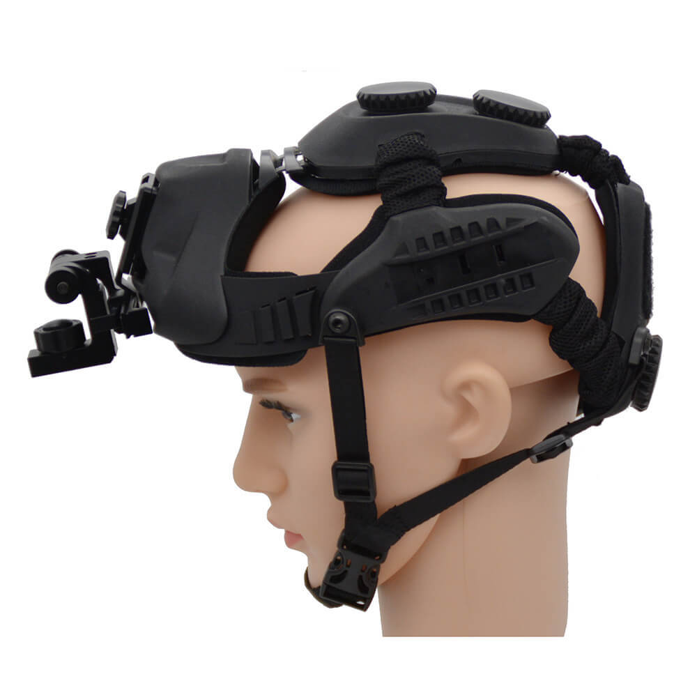
China Cheap price Optical Equipment - Night Vision Rifle Scope Weapon Sight Military Infrared Night Vision Monoculars – Detyl
China Cheap price Optical Equipment - Night Vision Rifle Scope Weapon Sight Military Infrared Night Vision Monoculars – Detyl Detail:
Product Specification
|
Model |
DT-NS85 |
|
IIT |
Gen 2+(Gen3) |
|
Magnification |
5X |
|
Resolution |
51-64 |
|
Detection distance(m) |
2000 |
|
Recognition |
1500 |
|
Lens system |
F1: 1.5, F105mm |
|
Pupil |
65mm |
|
FOV(deg) |
8.5 |
|
Distance of pupil |
50mm |
|
Graduation type |
Back Light red cursor |
|
Minimum mil |
1/8MOA |
|
Diopter range |
+/-5 |
|
Battery type |
CR123(A)x1 |
|
Battery life(H) |
40-50 |
|
range of focus (m) |
10–∞ |
|
Operating temperature(℃) |
-40 /+50 |
|
relative humidity |
5%-98% |
|
Impact strength |
>1000G |
|
Environmental rating |
IP65/IP67(Optional) |
|
Dimensions(mm) |
287x92x90(Containing eye mask and guide rai) |
|
Weight(g) |
960g(Containing guide rai |
Target reticle adjustment
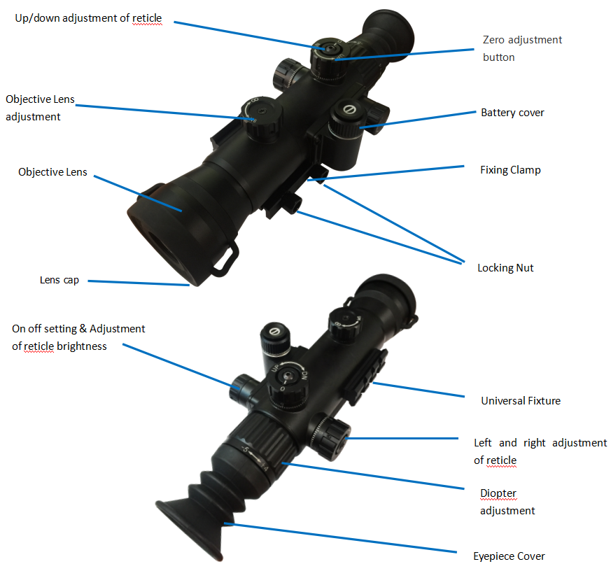
Adjustment of reticle brightness: as shown in figure ③, the ‘’off’’ knob is the first gear, and the ‘’ON’’ knob is the second gear. When the user needs to adjust the brightness of night vision graduation, turn the knob to the third gear, the fourth gear and the fifth gear in the on direction after ‘’ON’’, and the higher the gear is, the brighter the graduation brightness will be. The user can adjust the brightness to a suitable level according to personal preferences.
Up/down adjustment of reticle: when the user needs to adjust the up and down position of the night vision reticle, first, as shown in figure ⑥ – 1, stagger the position of “0″ and the indicating point, and then, as shown in figure ⑥ – 2, pull the knob up, turn the knob to adjust up and down, the up indicating direction is upward adjustment, and the DN indicating direction is downward adjustment. The user can adjust to the appropriate up and down position according to personal habits and preferences. After adjustment, press down the knob to lock it.
Left and right adjustment of reticle: when the user needs to adjust the left and right positions of the night vision reticle, first, as shown in figure ⑦-1, stagger the position of “0″ and the indicating point, and then, as shown in figure ⑦-2, pull the knob to the right, turn the knob to the left and right for adjustment. The L indicating direction is to the left, and the R indicating direction is to the right. The user can adjust it to the right and left position according to personal habits and preferences. After adjustment, press the knob to the left to lock it.
Zero adjustment
When the user needs to adjust the zero position, first align “0″ with the indication point, as shown in figure ⑧ – 1, then pull up and down (left and right) knobs to the highest position, as shown in figure ⑧ – 2, turn the position of adjusting the zero position to the position required by the user, and then press back to the lowest position for locking, as shown in figure ⑧ – 3, the zero position adjustment is completed. (the upper and lower knobs are adjusted in the same way as the left and right knobs)
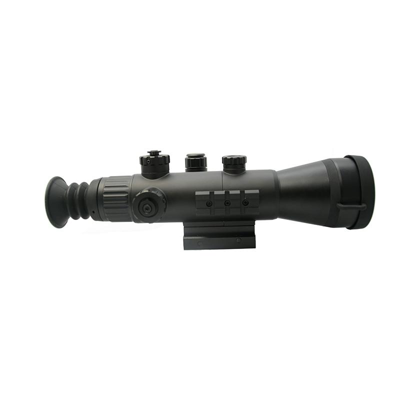
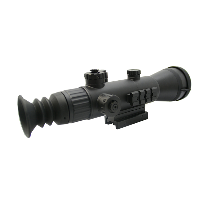
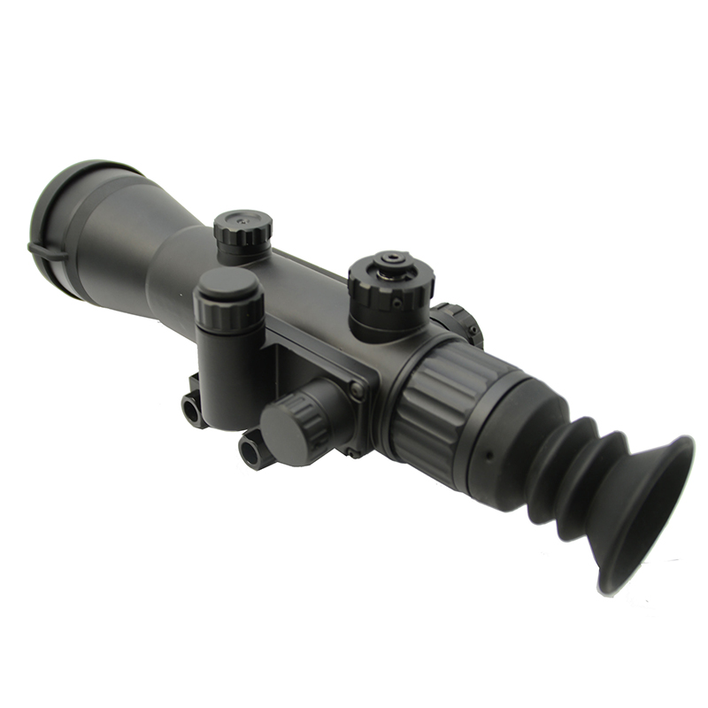
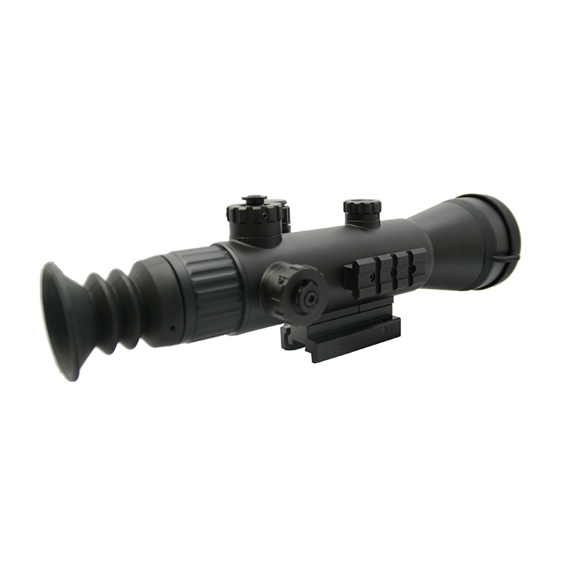
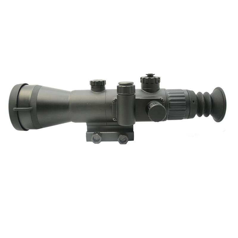
Product detail pictures:

Related Product Guide:
We have been ready to share our knowledge of advertising worldwide and recommend you suitable products at most aggressive costs. So Profi Tools present you ideal price of money and we've been ready to create with each other with China Cheap price Optical Equipment - Night Vision Rifle Scope Weapon Sight Military Infrared Night Vision Monoculars – Detyl , The product will supply to all over the world, such as: Philippines, Hyderabad, Jakarta, With nearly 30 years' experience in business, we are confident in superior service, quality and delivery. We warmly welcome customers from all over the world to cooperate with our company for common development.
As a veteran of this industry, we can say that the company can be a leader in the industry, select them is right.

